Your storage system supports physical network interfaces, such as Ethernet and Gigabit Ethernet interfaces, and virtual network interfaces, such as interface group and virtual local area network (VLAN). Each of these network interface types has its own naming convention.
Your storage system supports the following types of physical network interfaces:
- 10/100/1000 Ethernet
- Gigabit Ethernet (GbE)
- 10 Gigabit Ethernet
In addition, some storage system models include a physical network interface named e0M. The e0M interface is used only for Data ONTAP management activities, such as for running a Telnet, SSH, or RSH session. The following table lists interface types, interface name formats, and example of names that use these
identifiers.
Interface Type |
Interface Name Format |
Example |
Physical interface on a single-port adapter or slot |
e<slot_number> |
e0
e1 |
Physical interface on a multiple-port adapter or slot |
e<slot_number><port_letter> |
e0a
e0b
e1a
e1b |
Interface group |
Any user-specified string that meets certain criteria |
web_ifgrp
ifgrp1 |
VLAN |
<physical_interface_name>-<vlan-ID> or
<ifgrp_name>-<vlan_ID> |
e8-2
ifgrp1-3 |
Beginning with Data ONTAP 7.3, storage systems can accommodate from 256 to 1,024 network interfaces per system, depending on the storage system model, system memory, and whether they are in an HA pair. Each storage system can support up to 16 interface groups. The maximum number of VLANs that can be supported equals the maximum number of network interfaces shown in the following table minus the total number of physical interfaces, interface groups, vh, and loopback interfaces supported by the storage system.
You can manage your storage system locally from an Ethernet connection by using any network interface. However, to manage your storage system remotely, the system should have a Remote LAN Module (RLM) or Baseboard Management Controller (BMC). These provide remote platform management capabilities, including remote access, monitoring, troubleshooting, and alerting features.
Jumbo frames are larger than standard frames and require fewer frames. Therefore, you can reduce the CPU processing overhead by using jumbo frames with your network interfaces. Particularly, by using jumbo frames with a Gigabit or 10 Gigabit Ethernet infrastructure, you can significantly improve performance,depending on the network traffic. Jumbo frames are packets that are longer than the standard Ethernet (IEEE 802.3) frame size of 1,518 bytes. The frame size definition for jumbo frames is vendor-specific because jumbo frames are not part of the IEEE standard. The most commonly used jumbo frame size is 9,018 bytes. Jumbo frames can be used for all Gigabit and 10 Gigabit Ethernet interfaces that are supported on your storage system. The interfaces must be operating at or above 1,000 Mbps. You can set up jumbo frames on your storage system in the following two ways:
- During initial setup, the setup command prompts you to configure jumbo frames if you have an interface that supports jumbo frames on your storage system.
- If your system is already running, you can enable jumbo frames by setting the MTU size on an interface.
You can configure IP addresses for your network interface during system setup. To configure the IP addresses later, you should use the ifconfig command.
Display |
ifconfig -a
ifconfig <interface> |
IP address |
ifconfig e0 <IP Address>
ifconfig e0a <IP Address>
# Remove a IP Address
ifconfig e3 0 |
subnet mask |
ifconfig e0a netmask <subnet mask address> |
broadcast |
ifconfig e0a broadcast <broadcast address> |
media type |
ifconfig e0a mediatype 100tx-fd |
maximum transmission unit (MTU) |
ifconfig e8 mtusize 9000 |
Flow control |
ifconfig <interface_name> <flowcontrol> <value>
# example
ifconfig e8 flowcontrol none
Note: value is the flow control type. You can specify the following values for the flowcontrol option:
none - No flow control
receive - Able to receive flow control frames
send - Able to send flow control frames
full - Able to send and receive flow control frames
The default flowcontrol type is full.
|
trusted |
ifconfig e8 untrusted
Note: You can specify whether a network interface is trustworthy or untrustworthy. When you specify an interface as untrusted (untrustworthy), any packets received on the interface are likely to be dropped. |
HA Pair |
ifconfig e8 partner <IP Address>
## You must enable takeover on interface failures by entering the following commands:
options cf.takeover.on_network_interface_failure enable
ifconfig interface_name {nfo|-nfo}
nfo - Enables negotiated failover
-nfo - Disables negotiated failover
Note: In an HA pair, you can assign a partner IP address to a network interface. The network interface takes over this IP address when a failover occurs
|
Alias |
# Create alias
ifconfig e0 alias 192.0.2.30
# Remove alias
ifconfig e0 -alias 192.0.2.30 |
Block/Unblock protocols |
# Block
options interface.blocked.cifs e9
options interface.blocked.cifs e0a,e0b
# Unblock
options interface.blocked.cifs "" |
Stats |
ifstat
netstat
Note: there are many options to both these commands so I will leave to the man pages |
bring up/down an interface |
ifconfig <interface> up
ifconfig <interface> down |
Routing
You can have Data ONTAP route its own outbound packets to network interfaces. Although your storage system can have multiple network interfaces, it does not function as a router. However, it can route its outbound packets.
Data ONTAP uses two routing mechanisms:
- Fast path Data ONTAP uses this mechanism to route NFS packets over UDP and to route all TCP traffic.
- Routing table To route IP traffic that does not use fast path, Data ONTAP uses the information available in the local routing table. The routing table contains the routes that have been established and are currently in use, as well as the default route specification.
Fast path is an alternative routing mechanism to the routing table, in which the responses to incoming network traffic are sent back by using the same interface as the incoming traffic. It provides advantages such as load balancing between multiple network interfaces and improved storage system performance. Fast path is enabled automatically on your storage system; however, you can disable it. Using fast path provides the following advantages:
- Load balancing between multiple network interfaces on the same subnet. Load balancing is achieved by sending responses on the same interface of your storage system that receives the incoming requests.
- Increased storage system performance by skipping routing table lookups.
You can manage the routing table automatically by using the routed daemon, or manually by using the route command. The routed daemon performs the following functions by default:
- Deletes redirected routes after a specified period
- Performs router discovery with ICMP Router Discovery Protocol (IRDP) This is useful only if there is no static default route.
- Listens for Routing Information Protocol (RIP) packets
- Migrates routes to alternate interfaces when multiple interfaces are available on the same subnet
The routed daemon can also be configured to perform the following functions:
- Control RIP and IRDP behavior
- Generate RIP response messages that update a host route on your storage system
- Recognize distant gateways identified in the /etc/gateways file
If you are firmiliar with Unix routing then you should have no trouble with the following routing commands:
default route |
# using wrfile and rdfile edit the /etc/rc file with the below
route add default 192.168.0.254 1
# the full /etc/rc file will look like something below
hostname netapp1
ifconfig e0 192.168.0.10 netmask 255.255.255.0 mediatype 100tx-fd
route add default 192.168.0.254 1
routed on |
enable/disable fast path |
options ip.fastpath.enable {on|off}
Note:
on - Enables fast path
off - Disables fast path |
enable/disable routing daemon |
routed {on|off}
Note:
on - Turns on the routed daemon
off - Turns off the routed daemon |
Display routing table |
netstat -rn
route -s
routed status |
Add to routing table
|
route add 192.168.0.15 gateway.com 1 |
Hosts and DNS
Hosts and DNS are the same as Unix but here is a quick table just to jog your memory
Hosts |
# use wrfile and rdfile to read and edit /etc/hosts file , it basically use the sdame rules as a Unix
# hosts file
|
nsswitch file |
# use wrfile and rdfile to read and edit /etc/nsswitch.conf file , it basically uses the same rules as a
# Unix nsswitch.conf file
|
DNS |
# use wrfile and rdfile to read and edit /etc/resolv.conf file , it basically uses the same rules as a
# Unix resolv.conf file
options dns.enable {on|off}
Note:
on - Enables DNS
off - Disables DNS |
Domain Name |
options dns.domainname <domain> |
DNS cache |
options dns.cache.enable
options dns.cache.disable
# To flush the DNS cache
dns flush
# To see dns cache information
dns info |
DNS updates |
options dns.update.enable {on|off|secure}
Note:
on - Enables dynamic DNS updates
off - Disables dynamic DNS updates
secure - Enables secure dynamic DNS updates
|
time-to-live (TTL) |
options dns.update.ttl <time>
# Example
options dns.update.ttl 2h
Note: time can be set in seconds (s), minutes (m), or hours (h), with a minimum value of 600 seconds
and a maximum value of 24 hour
|
I will leave you to read the documentation regarding how to configure NIS.
VLAN
This section is a breif introduction into VLANs. VLANs provide logical segmentation of networks by creating separate broadcast domains. A VLAN can span multiple physical network segments. The end-stations belonging to a VLAN are related by function or application. For example, end-stations in a VLAN might be grouped by departments, such as engineering and accounting, or by projects, such as release1 and release2. Because physical proximity of the endstations is not essential in a VLAN, you can disperse the end-stations geographically and still contain the broadcast domain in a switched network.
An end-station must become a member of a VLAN before it can share the broadcast domain with other end-stations on that VLAN. The switch ports can be configured to belong to one or more VLANs (static registration), or end-stations can register their VLAN membership dynamically, with VLAN-aware switches. VLAN membership can be based on one of the following:
- Switch ports
- End-station MAC addresses
- Protocol
In Data ONTAP, VLAN membership is based on switch ports. With port-based VLANs, ports on the same or different switches can be grouped to create a VLAN. As a result, multiple VLANs can exist on a single switch.
Any broadcast or multicast packets originating from a member of a VLAN are confined only among the members of that VLAN. Communication between VLANs, therefore, must go through a router. The following figure illustrates how communication occurs between geographically dispersed VLAN members.
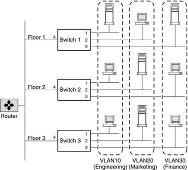
In this figure, VLAN 10 (Engineering), VLAN 20 (Marketing), and VLAN 30 (Finance) span three floors of a building. If a member of VLAN 10 on Floor 1 wants to communicate with a member of VLAN 10 on Floor 3, the communication occurs without going through the router, and packet flooding is limited to port 1 of Switch 2 and Switch 3 even if the destination MAC address to Switch 2 and Switch 3 is not known.
GARP VLAN Registration Protocol (GVRP) uses Generic Attribute Registration Protocol (GARP) toallow end-stations on a network to dynamically register their VLAN membership with GVRP-aware switches. Similarly, these switches dynamically register with other GVRP-aware switches on the network, thus creating a VLAN topology across the network. GVRP provides dynamic registration of VLAN membership; therefore, members can be added or removed from a VLAN at any time, saving the overhead of maintaining static VLAN configuration on switch ports. Additionally, VLAN membership information stays current, limiting the broadcast domain of a VLAN only to the active members of that VLAN.
By default, GVRP is disabled on all VLAN interfaces in Data ONTAP; however, you can enable it. After you enable GVRP on an interface, the VLAN interface informs the connecting switch about the VLANs it supports. This information (dynamic registration) is updated periodically. This information is also sent every time an interface comes up after being in the down state or whenever there is a change in the VLAN configuration of the interface.
A VLAN tag is a unique identifier that indicates the VLAN to which a frame belongs. Generally, a VLAN tag is included in the header of every frame sent by an end-station on a VLAN. On receiving a tagged frame, the switch inspects the frame header and, based on the VLAN tag, identifies the VLAN. The switch then forwards the frame to the destination in the identified VLAN. If the destination MAC address is unknown, the switch limits the flooding of the frame to ports that belong to the identified VLAN.
VLANs provide a number of advantages such as ease of administration, confinement of broadcast domains, reduced network traffic, and enforcement of security policies.
Create |
vlan create [-g {on|off}] ifname vlanid
# Create VLANs with identifiers 10, 20, and 30 on the interface e4 of a storage system by using the following command:
vlan create e4 10 20 30
# Configure the VLAN interface e4-10 by using the following command
ifconfig e4-10 192.168.0.11 netmask 255.255.255.0
|
Add |
vlan add e4 40 50 |
Delete |
# Delete specific VLAN
vlan delete e4 30
# Delete All VLANs on a interface
vlan delete e4 |
Enable/Disable GRVP on VLAN |
vlan modify -g {on|off} ifname |
Stat |
vlan stat <interface_name> <vlan_id>
# Examples
vlan stat e4
vlan stat e4 10 |
Interface Groups
An interface group is a feature in Data ONTAP that implements link aggregation on your storage system. Interface groups provide a mechanism to group together multiple network interfaces (links) into one logical interface (aggregate). After an interface group is created, it is indistinguishable from a physical network interface.
Interface groups provide several advantages over individual network interfaces:
- Higher throughput Multiple interfaces work as one interface.
- Fault tolerance If one interface in an interface group goes down, your storage system stays connected to the network by using the other interfaces.
- No single point of failureIf the physical interfaces in an interface group are connected to multiple switches and a switchgoes down, your storage system stays connected to the network through the other switches.
You can create three different types of interface groups on your storage system: single-mode interface groups, static multimode interface groups, and dynamic multimode interface groups. Each interface group provides different levels of fault tolerance. Multimode interface groups provide methods for load balancing network traffic.
In a single-mode interface group, only one of the interfaces in the interface group is active. The other interfaces are on standby, ready to take over if the active interface fails. All interfaces in a singlemode interface group share a common MAC address. There can be more than one interface on standby in a single-mode interface group. If an active interface fails, your storage system randomly picks one of the standby interfaces to be the next active link. The active link is monitored and link failover is controlled by the storage system; therefore, single-mode interface group does not require any switch configuration. Single-mode interface groups also do not require a switch that supports link aggregation.
Dynamic multimode interface groups can detect not only the loss of link status (as do static multimode interface groups), but also a loss of data flow. This feature makes dynamic multimode interface groups compatible with high-availability environments. The dynamic multimode interface group implementation in Data ONTAP is in compliance with IEEE 802.3ad (dynamic), also known as Link Aggregation Control Protocol (LACP). Dynamic multimode interface groups have some special requirements. They include the following:
- Dynamic multimode interface groups must be connected to a switch that supports LACP.
- Dynamic multimode interface groups must be configured as first-level interface groups.
- Dynamic multimode interface groups should be configured to use the IP-based load-balancing method.
In a dynamic multimode interface group, all interfaces in the interface group are active and share a single MAC address. This logical aggregation of interfaces provides higher throughput than a singlemode interface group. A dynamic multimode interface group requires a switch that supports link aggregation over multiple switch ports. The switch is configured so that all ports to which links of an interface group are connected are part of a single logical port. For information about configuring the switch, see your switch vendor's documentation. Some switches might not support link aggregation of ports configured for jumbo frames.
The load-balancing method for a multimode interface group can be specified only when the interface group is created. If no method is specified, the IP address based load-balancing method is used.
Create (single-mode) |
# To create a single-mode interface group, enter the following command:
ifgrp create single SingleTrunk1 e0 e1 e2 e3
# To configure an IP address of 192.168.0.10 and a netmask of 255.255.255.0 on the singlemode interface group SingleTrunk1
ifconfig SingleTrunk1 192.168.0.10 netmask 255.255.255.0
# To specify the interface e1 as preferred
ifgrp favor e1
|
Create ( multi-mode) |
# To create a static multimode interface group, comprising interfaces e0, e1, e2, and e3 and using MAC
# address load balancing
ifgrp create multi MultiTrunk1 -b mac e0 e1 e2 e3
# To create a dynamic multimode interface group, comprising interfaces e0, e1, e2, and e3 and using IP
# address based load balancing
ifgrp create lacp MultiTrunk1 -b ip e0 e1 e2 e3
|
Create second level intreface group |
# To create two interface groups and a second-level interface group. In this example, IP address load
# balancing is used for the multimode interface groups.
ifgrp create multi Firstlev1 e0 e1
ifgrp create multi Firstlev2 e2 e3
ifgrp create single Secondlev Firstlev1 Firstlev2
# To enable failover to a multimode interface group with higher aggregate bandwidth when one or more of
# the links in the active multimode interface group fail
options ifgrp.failover.link_degraded on
Note: You can create a second-level interface group by using two multimode interface groups. Secondlevel interface groups enable you to provide a standby multimode interface group in case the primary multimode interface group fails.
|
Create second level intreface group in a HA pair |
# Use the following commands to create a second-level interface group in an HA pair. In this example,
# IP-based load balancing is used for the multimode interface groups.
# On StorageSystem1:
ifgrp create multi Firstlev1 e1 e2
ifgrp create multi Firstlev2 e3 e4
ifgrp create single Secondlev1 Firstlev1 Firstlev2
# On StorageSystem2 :
ifgrp create multi Firstlev3 e5 e6
ifgrp create multi Firstlev4 e7 e8
ifgrp create single Secondlev2 Firstlev3 Firstlev4
# On StorageSystem1:
ifconfig Secondlev1 partner Secondlev2
# On StorageSystem2 :
ifconfig Secondlev2 partner Secondlev1 |
Favoured/non-favoured interface |
# select favoured interface
ifgrp nofavor e3
# select a non-flavoured interface
ifgrp nofavor e3
|
Add |
ifgrp add MultiTrunk1 e4 |
Delete |
ifconfig MultiTrunk1 down
ifgrp delete MultiTrunk1 e4
Note: You must configure the interface group to the down state before you can delete a network interface
from the interface group |
Destroy |
ifconfig ifgrp_name down
ifgrp destroy ifgrp_name
Note: You must configure the interface group to the down state before you can delete a network interface
from the interface group
|
Enable/disable a interface group |
ifconfig ifgrp_name up
ifconfig ifgrp_name down |
Status |
ifgrp status [ifgrp_name] |
Stat |
ifgrp stat [ifgrp_name] [interval] |
Diagnostic Tools
There are a number of tools and options that you can use to help with network related problems
Useful options
|
Ping thottling |
# Throttle ping
options ip.ping_throttle.drop_level <packets_per_second>
# Disable ping throttling
options ip.ping_throttle.drop_level 0 |
Forged IMCP attacks |
options ip.icmp_ignore_redirect.enable on
Note: You can disable ICMP redirect messages to protect your storage system against forged ICMP redirect attacks. |
Useful Commands
|
netdiag |
The netdiag command continuously gathers and analyzes statistics, and performs diagnostic tests. These diagnostic tests identify and report problems with your physical network or transport layers and suggest remedial action.
|
ping |
You can use the ping command to test whether your storage system can reach other hosts on your network. |
pktt |
You can use the pktt command to trace the packets sent and received in the storage system's network. |